- Amplatzer PFO Occluder
- Implanting the Amplatzer PFO Occluder
- Implantation Views of the Amplatzer PFO Occluder
AMPLATZER® PFO Occluder
Device Description
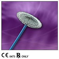
The AMPLATZER PFO Occluder is a self-expandable, double disc device made from a Nitinol wire mesh. The two discs are linked together by a short, connecting waist, allowing free motion of each disc.
In order to increase its closing ability, the discs contain thin polyester fabric. This fabric is securely sewn to each disc by a polyester thread.
The AMPLATZER PFO Occluder has been developed to be potentially used as an alternative to either open heart surgery or anticoagulant/antiplatelet therapy. Currently, these are the two measures most commonly taken to prevent further recurrences in patients with PFO and paradoxical cerebral emboli.
Outside the U.S.A.
Intended Use
The AMPLATZER PFO Occluder is a percutaneous, transcatheter occlusion device intended to close all types of PFO's (i.e., classical as well as those with aneurysm of the septum) in patients with a history of stroke or transient ischemic attacks (TIA's)).
U.S.A.
Humanitarian Use Device
The AMPLATZER PFO Occluder is authorized by Federal law for the non-surgical closure of a patent foramen ovale (PFO) in patients with recurrent cryptogenic stroke(1) due to presumed paradoxical embolism through a patent foramen ovale and who have failed conventional drug therapy(2). The effectiveness of this device for use in this indication has not yet been demonstrated.
Footnotes:
- Cryptogenic stroke - a stroke occurring in the absence of potential phanerogenic cardiac, pulmonary, vascular or neurological sources.
- Conventional drug therapy - a therapeutic international normalized ratio (INR) on oral anticoagulants
Copyright © 1997-2003, AGA Medical Corporation, Golden Valley, Minnesota, USA. All rights reserved.
All information is sole property of AGA Medical Corporation.
If you have patients that you would feel could benefit please feel free to contact Dr. Micky Wheatley at (615) 515-1900 or (toll free) at (866) 515-0019.
Implanting the AMPLATZER® PFO Occluder
- Using Four Chamber view, measure the distance from the rim of the defect to the rim of the superior atrial wall (Figure 1, #2).
- Using TEE Short Axis view, measure the distance from the rim of the defect to the aortic mound (anterior superior rim) (Figure 2, #7).
Figure 1
Four Chamber View
- Total Septal Length measured at maximal atrial dimension.
- Superior vena cava to the edge of the defect.
- Pulmonary vein to edge of defect.
- Edge of defect to mitral valve.
Measurements #2 and #7 Select:
If both are: 17.5 mm or greater - 9-PFO-HDE-035
If either are: 12.5 to 17.5 - 9-PFO-HDE-025
If either are: 9 to 12.5 mm - 9-PFO-HDE-018
If either are: Less than 9 mm - Do not implant device
WARNING: Do not implant a device if the distance from the PFO to the free atrial wall is less than 12.5 mm (as measured by echo). - Posterior rim length.
- Posterior rim to the edge of the defect.
- The distance from the edge of the defect to the aortic mound (which is the Anterior Superior Rim). If the septal primum and limbus fossae ovalis form a tunnel, measure the distance from the right atrial aspect of the tunnel to the aortic mound.
Figure 2
strong>TEE Short Axis View
Directions for use:
- Patients should be fully heparinized throughout the procedure using adequate dosing so as to keep the ACT greater than 200 msec.
- Following percutaneous puncture of the femoral vein, perform a standard right heart catheterization. Pass a diagnostic catheter through the PFO into the left atrium and introduce an exchange “J” guidewire (2 cm tip) into the left atrium.
- Using transesophageal echocardiography (TEE) or similar imaging equipment (i.e, intracardiac echocardiography), measure the distance of the defect to the free atrial wall, atrial septal size and distance to surrounding structures (reference 8.3 for device selection).
- Pass the delivery cable through the loader and screw the device on to the delivery cable.
- Once the device is securely attached to the cable, immerse the device and loader in saline solution and pull the device into the loader.
- Remove the catheter leaving the guidewire in place.
- Insert the dilator into the delivery sheath and secure to the sheath with the locking mechanism. Introduce the dilator/delivery sheath assembly. Once the delivery sheath has reached the inferior vena cava, remove the dilator to allow back bleeding to purge all air from the system.
- Connect the hemostasis valve and flush with a syringe before the left atrium is entered.
- Advance the sheath over the guidewire through the PFO and into the left atrium. Correct position of the delivery sheath is verified by a test injection of contrast medium. Once in satisfactory position, remove the guidewire and flush the sheath with saline.
- Introduce the loading device to the delivery sheath. Advance the device into the sheath by pushing (not rotating) the delivery cable.
 Under fluoroscopic and echocardiographic guidance, deploy the left atrial disc by pulling firmly against the atrial septum, which can be felt and observed via ultrasonography.
 With gentle tension on the delivery cable, pull the sheath back to deploy the right atrial disc. To and fro motion with the delivery cable assures secure position across the patent foramen ovale, which can be observed by ultrasound and fluoroscopy.
- Confirm correct placement. Advance the sheath close to the right atrial disc and administer an injection of contrast medium to confirm correct position.
WARNING: Careful assessment of the edge of the device along the free atrial wall by echocardiography and angiography must be completed. If the device is in contact with the free atrial wall, the device must be removed and replaced with a smaller device, if available or the procedure abandoned.  Release the device. Attach the plastic vise to the delivery cable, tighten the screw and unscrew the device from the cable by turning the cable counterclockwise (indicated by the arrow on the vise). In the unlikely event that this should not be possible, the sheath can be advanced against the right atrial disc to fix the device which facilitates detachment.
WARNING: Do not release the AMPLATZER PFO Occluder from the delivery cable if the device does not conform to its original configuration or if the device position is unstable. Recapture the device and redeploy. If still unsatisfactory, recapture the device and replace with a new device.
Copyright © 1997-2003, AGA Medical Corporation, Golden Valley, Minnesota, USA. All rights reserved.
All information is sole property of AGA Medical Corporation.
If you have patients that you would feel could benefit please feel free to contact Dr. Micky Wheatley at (615) 515-1900 or (toll free) (866) 515-0019.
Contrast test injection demonstrating a classical type Patent Foramen Ovale.
Valsalva Maneuver Pre-PFO Closure.
Pre Release
Post Release.
Post closure Arteriogram after implantation of an AMPLATZER PFO Occluder demonstrating complete closure of the defect.
Valsalva Maneuver Post-PFO Closure.
TEE view demonstrating a PFO with large aneurysm of the septum.
Base of the Aneurysm.
Note the large mobility of the flap.
TEE view of THE 35mm AMPLATZER PFO Occluder post implantation. The aneurysmal tissue has been secured and the defect is closed.
Images courtesy of:
Felix Berger MD, Vice Director, Dept.of Congenital Heart Disease
Deutsches Herzzentrum Berlin, Berlin, Germany
Copyright © 1997-2003, AGA Medical Corporation, Golden Valley, Minnesota, USA.
All rights reserved. All information is sole property of AGA Medical Corporation.